Decided to make a demo of the Schmidt coupling. The measurements were taken from a computer printout.
The source of the 'computer printout' is not clear. It may be from one of the 'German' mechanical devices located in the folder "Documents/Metalworking/Mechanical Devices."
For a 3.5" disk 1 7/8" connecting rods are needed as measured from connecting point to connecting point. The connecting rods are planned to be 5/8" wide with a 5/16" radius at each end. The connecting points are 2 1/2" apart on each disk. The total length of each rod is 2 1/2". The connecting points sit on a circle of radius 1 7/16". Made the device half-size per the following discussion.
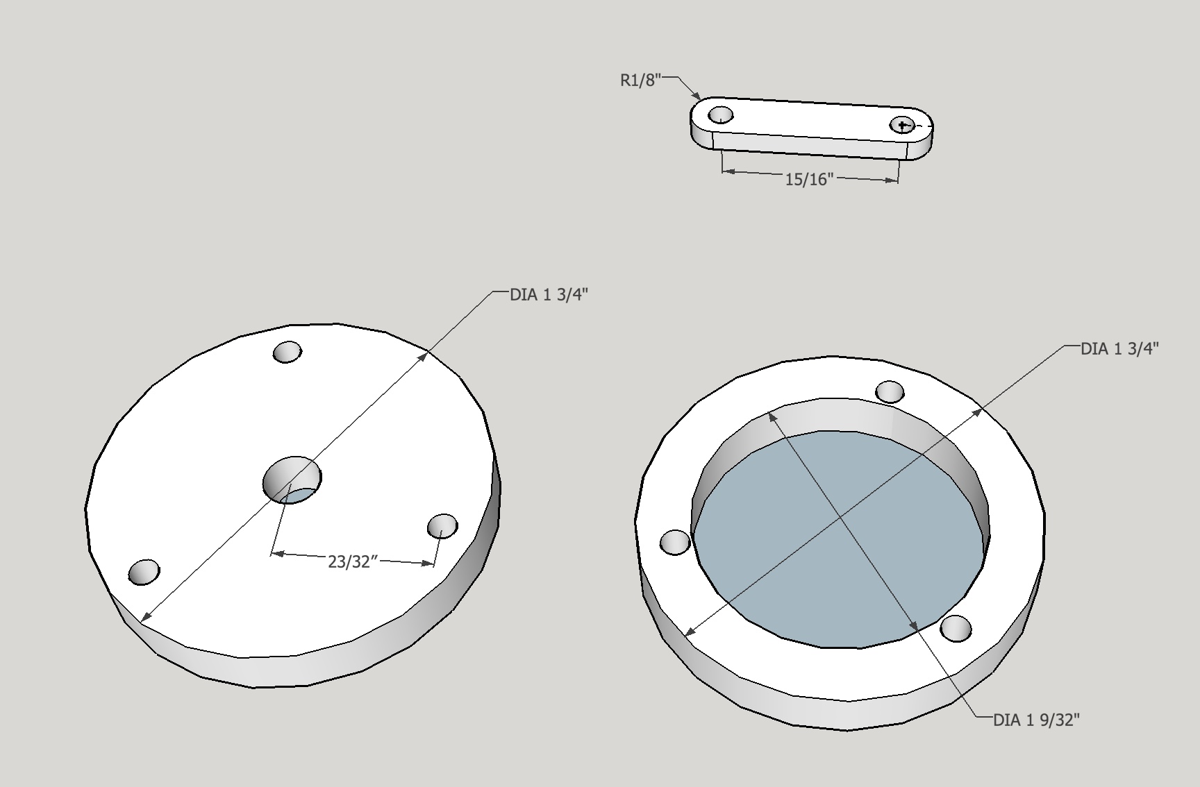
It is not clear how best to connect the disks and rods. Also need to decide the scale of the device. The plan is to make a custom fit screw for the connections if purchased screws do not work. Decided that the scale should be 1/2 the original. This sets the disk size at 1.75" and the connecting rods at 1.25" with a 0.9375" hole spacing. The bolt hole radius is also 0.9375".
The connecting rods were cut four at a time to length on the mill and then cut to width. They were cut to width with a fly cutter. The edges were cleaned up with a file. Holes were located at 1.25" - 0.9375" = 0.3125"/2 = 0.156" in from each end. Four pieces were lined up in the vise and the side and ends were located. The hole location was centered under the spindle and the parts were center drilled and drilled with a #29 drill bit (0.136"). This is equal to the OD of a 6-32 screw. The parts were switched end for end and the new end located. Again center drilling was followed by drilling with the #29 drill bit. This was then repeated for the second set of four connecting rods.
Two of the parts in this second batch were slightly narrower than the other two so the four were shimmed with a piece of paper.
All of the connecting rods were cleaned up with a file. Two aluminum disks (1.75" in diameter) were faced on both sides and the thickness was reduced to 0.25". They were center drilled and drilled with a #7 drill bit. They were both then tapped 1/4-20.
A 1/4" X 1 3/4" square of brass was centered in the four-jaw chuck by lining up the center mark with a gauge. It was center drilled and drilled through with a #7 drill bit. It was then threaded with a 1/4-20 tap.
It was necessary to repeat this work on the brass as the first hole was not straight! Not sure if this was because the part was not set right in the four-jaw chuck or the tap went in crooked.
A bolt was placed in the hole and the work piece was bracketed by two nuts. It was then reduced to a circle on the lathe. This part was then placed in the three-jaw chuck and drilled to 1/2" and bored to leave a 0.31" width ring. Thus the holes were centered at 23/32" from the middle.
Holes were drilled through centers of the two aluminum disks. A disk was threaded onto a bolt and locked in place with nuts on both sides. The lower bolt was clamped in the vise and the edge of the disk was located. A hole was drilled 5/32" in from the edge of the disk. The hole was drilled with a #36 drill bit for a 6-32 screw. The hole was tapped. The edge was relocaed prior to drilling each of the next two holes.
One hole was off with respect to the angle from previous hole?! A second hole was drilled in the correct position.
The aluminum disk was used as a template for the brass ring. (Should have cut the holes in the brass prior to boring the center.) A ruler was used to determine the exact location of the second set of three holes in the brass ring.
Assembling two parts with screws indicates a 3/16" spacer is required. To this end a length of 5/16" brass rod was center drilled and drilled with a #29 drill bit through. The cutoff tool was then used to make 12 spacers. The remaining 3/4" of brass tube was used as a jig. A bolt was run through it and connecting rods were mounted on the bolt. The brass tube was held in the vise and the connecting rods were turned into the milling cutter.
Should have used some sort of clamp as a handle to turn the connecting rods!!!!
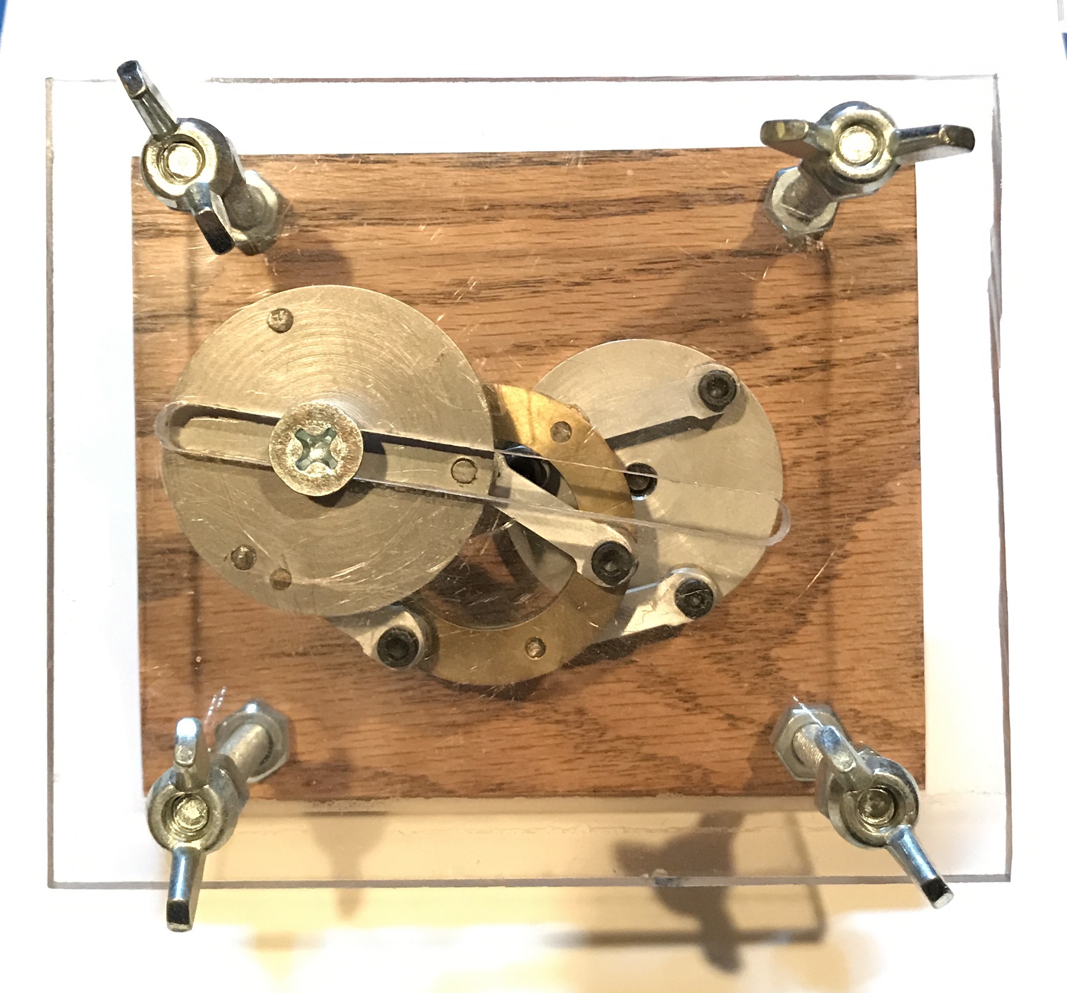
The assembled mechanism was a little taller than 1 3/4". The back for the case was made of 3/4" red oak cut to 4" X 5". The front was made from 1/4" polyacrylic sheet. Holes were cut in all four corners of each. The back of the wood was bored 3/8" deep with a 1/2" Forstner bit in the four corners as countersinks for the 4 bolt heads. A hole was then drilled for the drive axle, 1 5/8" from the top and centered left/right.
The connecting rods were thinned across the middle for aesthetic reasons. The was done by removing about 0.05" from each side of the rod.
The mechanism was assembled by putting screws through the connecting rods and spacers and into the disks. Loctite was put on the ends of the screws in the aluminum disks to keep them from unscrewing. These two assemblies were allowed to dry. Both were then attached to the brass ring. A small rod of brass (0.25" X 0.106") was glued into the 'extra' hole in one of the aluminum disks.
Finally a crank was simply made. A bolt through the back was run through a 1.25" long connecting rod that had a set screw to hold it tight. A 1/4" rod had one end reduced to 1/8". This small end went through a hole drilled in the opposite end of the connecting rod and was then peened to retain.
The mechanism needs some modifications before it will ever work smoothly! The most important change would be to carefully mark out the locations of the ring holes where the connecting rods attach. (Mark out the bolt hole circle and inscribe a triangle.) Second would be to use dowels instead of screws for better movement of the rods with respect to the disks.